
This tutorial describes how to get started with our Ethernet cores on NUMATO LAB Mimas A7 development board.
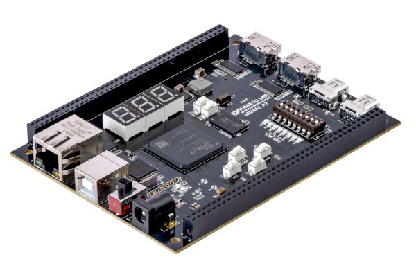
The board has one Artix XC7A50T from Xilinx and a RGMII Ethernet interface supporting gigabit Ethernet. The PHY on board is a RTL8211E from Realtek.
We will use the FC1004_RGMII core. It has Remote Programming, TCP/IP Server, UDP Server and Logic Analyzer support.
This tutorial uses Vivado Design Suite from Xilinx to build the project.
Requirements
- Xilinx Vivado installed
- NUMATO LAB Mimas A7 board connected to a JTAG programmer and Ethernet
Create a new Vivado project.
- [File]-[New Project…]
- Select RTL Project.
- Don’t add any source or constraint files now.
- Select xc7a50tfgg484-1
Download Files
- Download FC1004_RGMII to the project folder.
- Download MimasTop.vhd the project folder.
- Download MimasA7.xdc the project folder.
Add Sources to the project
- [File]-[Add Sources…]
- Select Add or Create Design Resources
- Add the files MimasTop.vhd and FC1004_RGMII.edn
- [File]-[Add Sources…]
- Select Add or Create Constraints
- Add the file MimasA7.xdc
Turn off DHCP Option only if necessary
The Top file is using static IP Address 192.168.1.15 as default. If you want to use DHCP IP then:
- Open the MimasTop.vhd in an editor
- Set the port signal UseDHCP to ‘1’
Set Bitstream settings
The FPGA Remote programmer uses the bin file format when programming the FPGA.
- [Flow]-[Settings]-[Bitstream Settings…]
- Check the -bin_file option
Build the project.
- [Flow]-[Generate Bitstream]
Download bit file
First time we need to program the bit/bin file with JTAG. After that we can use the FPGA Programmer.
- Open Hardware Manager
- Auto Connect
- Select the generated bit file and program the FPGA
Program the flash with FPGA Programmer via Ethernet
- If FPGA Programmer is not installed then download and install FPGA Programmer.
- Start FPGA Programmer
- Select the generated bin file and program the Mimas A7 Board. This file is typically found in ./ProjectName.runs/impl_1/.
- Check all options (Program, Verify, Reboot)
- Press Run to start the flash programming
From now you only need to have the board connected to Ethernet to update and program the board.
Use the logic analyzer FPGA Probe
- If FPGA Probe is not installed then download and install FPGA Probe.
- Start FPGA Probe
- Select the FPGAs IP
- Make sure Play button is active
There should now be some bit action on the screen.
You can now try to alter the top file to generate some other data in the logic analyzer.
You can now also easily use the TCP/UDP AXI4 Streams to communicate with the board via a Windows or Linux client.
This example uses TCP port 22 as default. That is Telnet standard. You can use any terminal program e.g. Putty and connect Telnet port 22 to address 192.168.1.15. All received bytes are echoed i.e. you will see all bytes you type double. The value of the last written byte is displayed on the LEDs.
Have fun!