
Wishbone is an open source standard bus that connects slave peripherals to a master CPU. Instant SoC V1.2 supports Wishbone and you can easily add your own VHDL or Verilog peripherals to the Instant SoC RISC-V system. Instant SoC supports the B4 version of Wishbone.
To add a Wishbone component you simply creates a FC_Wishbone object in C++ with a file path to the component and Instant SoC adds the component and maps all Wishbone bus signals to the system. The file could be a Verilog (*.v) or VHDL (*.vhd) source file. You can add any number of the component to the system.
The following example shows the C++ code to add two PWM modules and two encoders to the system.
#include "FC_System.h"
#indlude "FC_IO.h"

void main()
{
 //% hw_begin
    FC_IO_Clk clk(100);         // 100 MHz
    FC_Wishbone pwm_1("PWM_HiLo.v");
    FC_Wishbone pwm_2("PWM_HiLo.v");
    FC_Wishbone enc_1("QEncoder.vhd");
    FC_Wishbone enc_2("QEncoder.vhd");
//% hw_end

    // Reset enc_1
    enc_1.Reset();

    // Write 1000 to pwm_1 addr 2
    pwm_1.Write(1000, 2);
    ...
    // Read addr 0 from enc_1
    int pos = enc_1.Read(0);
    ...
}
The Wishbone signals are automatically mapped inside the SoC system. Non Wishbone signals are exposed out from the generated system component. The name of the exposed signals are the same as the component signals names with the C++ object name added. In the example above the generated system port will look like the following.
entity wishbone is
    port(
        clk            : in std_logic;    --  100 MHz
        pwm_1_pulse_hi : out std_logic;
        pwm_1_pulse_lo : out std_logic;
        pwm_2_pulse_hi : out std_logic;
        pwm_2_pulse_lo : out std_logic;
        enc_1_A        : in std_logic;
        enc_1_B        : in std_logic;
        enc_2_A        : in std_logic;
        enc_2_B        : in std_logic
    );
end entity;
The PWM component in the example is written in Verilog. The address width is two, i.e. four registers. The read/write data width is 16. The port looks like following.
module PWM_HiLo
(
    // --- Example external signals ---
    output reg pulse_hi,
    output reg pulse_lo,

    // --- Wishbone Signals ---
    input  wire CLK_I,
    input  wire RST_I,
    input  wire [1:0] ADR_I,
    output reg  [15:0] DAT_O,
    input  wire [15:0] DAT_I,
    input  wire WE_I,
    input  wire STB_I,
    output reg  ACK_O,
    input  wire CYC_I
);
The quadrature encoder component in the example is written in VHDL. It has only one read register that is 32 bits wide. The port looks like the following.
entity QEncoder is
port (
    --- Example external signals ---
    A : in std_logic;
    B : in std_logic;

    --- Wishbone Signals ---
    CLK_I : in std_logic;
    RST_I : in std_logic;
    DAT_O : out std_logic_vector(31 downto 0);
    STB_I : in std_logic;
    ACK_O : out std_logic;
    CYC_I : in std_logic
);
end entity;
Instant SoC parses the input source file signals and optimizes the system regarding to the component’s address and data width with minimal overhead.
Wishbone Slave Signals
Instant SoC supports the following Wishbone signals.
| CLK_I | In | Clock input. Mandatory. This is the same clock as the system clock, FC_IO_Clk |
| RST_I | In | Reset input. Active high. Reset is active when system starts or called by FC_Wishbone::Reset() |
| ADR_I | In | Address input for read and write cycles. Optional. Width from 1 to 32. |
| DAT_O | Out | Data out from component. Optional. Width from 1 to 32. |
| DAT_I | In | Data in to component. Optional. Width from 1 to 32. |
| WE_I | In | Write Enable. Indicates a write cycle. Optional. |
| STB_I | In | Indicates a valid data transfer |
| ACK_O | Out | Acknowledge output. Terminates a normal bus cycle. |
| CYC_I | In | Indicates a valid bus cycle. Typically this is same as STB_I signal. |
Note that the signal names must be spelled exactly like the signal names in the table above.
As a minimum, the SLAVE interface MUST include the following signals: [ACK_O] , [CLK_I], [CYC_I], [STB_I], and [RST_I].
Create a Wishbone Slave Template
Instant SoC can generate a template that is a good starting point for your peripheral. Use the FC_Wishbone C++ constructor with a file name and address/data width arguments. If the file doesn’t exists Instant SoC will create the file and write a very simple component. Both Verilog and VHDL temple creation are supported. If the file name is (*.v) a Verilog source file is created. If the file name is (*.vhd) or (*.vhdl) a VHDL source file is created.
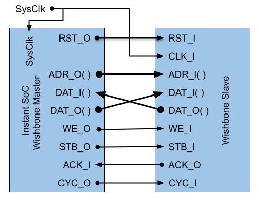
Expose the Wishbone Master Signals
It is also possible to expose the Master Wishbone signals if you want to map the signals outside the generated system. This is done by creating a FC_Wishbone object without a source file. You specify data and adress width.
In the following example a 16 x 32 bits register component is created.
#include "fc_io.h"
#include "fc_system.h"

int main()
{
//% hw_begin
    FC_IO_Clk clk(100);         // 100 MHz
    FC_Wishbone wb(4,32,32);
//% hw_end

    wb.Write(0x1234,0); // Write 0x1234 to addr 0

    int read = wb.Read(1); // Read addr 1

    for(;;)
    {
    // Do something...
    }
}
When building the C++ example code above a system is generated with the following VHDL port.
entity wishbone_example2 is
    port(
        clk      : in  std_logic;    --  100 MHz
        wb_RST_O : out std_logic;
        wb_ADR_O : out std_logic_vector(3 downto 0);
        wb_DAT_I : in  std_logic_vector(31 downto 0);
        wb_DAT_O : out std_logic_vector(31 downto 0);
        wb_WE_O  : out std_logic;
        wb_STB_O : out std_logic;
        wb_ACK_I : in  std_logic;
        wb_CYC_O : out std_logic
    );
end entity;