
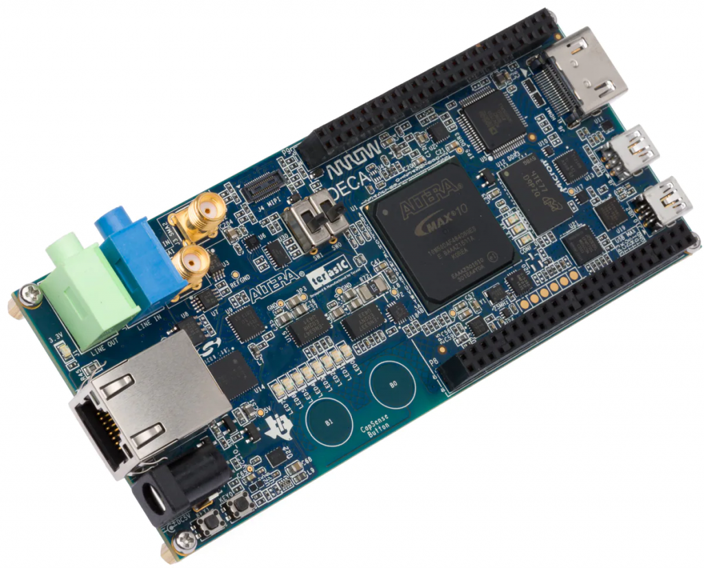
DECA board is a development board from Arrow containing a Max 10 FPGA from Intel Altera. The board contains a lot of hardware like Ethernet, touch buttons, accelerometer, sound codec and more.
In this tutorial we will use Instant SoC to create a moving LED that is controlled by the accelerometer x-axis. When leaning the board the active LED will drop in that direction. We will also use PWM outputs to control the LED’s fading trace.
When compiling a C++ file with Instant SoC all necessary hardware and software to run the code is created. The hardware includes a RISC-V CPU core that is highly optimized for the generated code.
It is assumed that the reader is familiar with using Quartus software from Intel/Altera and understands C++.
Please read the Quartus Intel/Altera page to set up the project properly. Make sure to use Instant SoC 1.3 or later.
We will first do a very simple blinking light that is using FC_System_Timer and FC_IO_Out classes.
Create a directory that will contain the project. If you work in Windows use the Instant SoC application to setup this directory and if you work in Linux you use the make_soc command.
Start Visual Studio Code and create a “deca.cpp” C++ file and write the following necessary lines to create a minimal Instant SoC system. This simple code will alternate the four left leds and the four right leds with a period of 1 sec.
#include "fc_io.h"
#include "fc_system.h"

int main()
{
    // Define the hardware
    //% hw_begin
    FC_IO_Clk clk(50);              // 50 MHz clock
    FC_IO_Out led(8);               // 8 LEDs controlled by PWM
    FC_System_Timer timer;
    //% hw_end

    for(;;) {
        timer.Sleep(500, TU_ms);
        led = 0x0F;
        timer.Sleep(500, TU_ms);
        led = 0xF0;
    }
}
Press Ctrl+Shift+B to build the system. We will use the generated “deca.vhd” file as our top-level entity.
Open Quartus and create a new project with 10M50DAF484 MAX 10 FPGA as device. Add the generated “deca.vhd” file to your project. Define the following pins locations.
PIN_M8 clk 50 MHz
PIN_C7 led[0]
PIN_C8 led[1]
PIN_A6 led[2]
PIN_B7 led[3]
PIN_C4 led[4]
PIN_A5 led[5]
PIN_B4 led[6]
PIN_C5 led[7]
In Quartus build the project and download the bit-stream to the DECA board. You will now see the 8 LEDs blinking.
You can now play around a little with the timer and led to create your own blinking patterns.
The accelerometer is LIS2DH12 from ST. It is a 3 axis MEMS device supporting both I2C and SPI digital interfaces.
We will now add the SPI interface to read accelerometer values from the LIS2DH12 device. We will run the SPI interface at 1 Mbps. We also use PWM to control the LEDs. Modify the hardware definition section to the following. The LIS2DH12 device will use SPI mode 3, CPOL=1 and CPHA=1. In this case we only need a very small FIFO, 4 bytes.
int main()
{
    // Define the hardware
    //% hw_begin
    FC_IO_Clk clk(50);              // 50 MHz clock
    FC_IO_PWM led(8);               // 8 LEDs controlled by PWM
    FC_IO_SPI accel(1000000,3,4);   // SPI accelerometer, mode=3, 4bytes FIFO
    FC_System_Timer timer;
    //% hw_end
Set pin locations for the accelerometer SPI interface.
PIN_E9 accel_SSn
PIN_B5 accel_SCLK
PIN_D5 accel_MISO
PIN_C6 accel_MOSI
Add the following two function to read and write registers in the accelerometer device.
U8 ReadAccReg(FC_IO_SPI& accel, U8 reg)
{
    accel.ResetReadFIFO();
    U8 spi_cmd [2];
    spi_cmd[0] = 0x80|reg;
    spi_cmd[1] = 0x00;
    accel.StartWrite(spi_cmd,2);
    while(accel.GetNumValid() < 2)
    {}
    accel.Read(spi_cmd,2);
    return spi_cmd[1];
}

void SetAccReg(FC_IO_SPI& accel, U8 reg, U8 data)
{
    accel.ResetReadFIFO();
    U8 spi_cmd [2];
    spi_cmd[0] = reg;
    spi_cmd[1] = data;
    accel.StartWrite(spi_cmd,2);
    while(accel.GetNumValid() < 2)
    {}
}
Edit the main() function to the following. The code should be self explained and easy to understand.
int main()
{
    // Define the hardware
    //% hw_begin
    FC_IO_Clk clk(50);              // 50 MHz clock
    FC_IO_PWM led(8);               // 8 LEDs controlled by PWM
    FC_IO_SPI accel(1000000,3,4);   // SPI accelerometer
    FC_System_Timer timer;
    //% hw_end

    // Init Accelerometer
    SetAccReg(accel, 0x20, 0x97);   // CTRL_REG1 (20h)
    SetAccReg(accel, 0x23, 0xb8);   // CTRL_REG4 (23h)

    // Set up PWMs/LEDs
    led.Setup(100, TU_clk);         // PWM duty cycle 100 clks

    int pwm_on[8];
    for(int i=0;i<8;i++)
        pwm_on[i] = 0;

    short acc[3];   // Accelerometer values x,y,z
    int pos = 0;    // Active LED

    for(;;) {   // Infinite loop

        U8 reg = 0x28;  // First address
        for(int i=0;i<3;i++) {
            acc[i] = (ReadAccReg(accel,reg++) );   // Read accelerometer low 8 bits
            acc[i] |= (ReadAccReg(accel,reg++) << 8 );   // Read accelerometer low 8 bits
        }

        pos += (acc[0]>>5);         // X axis accelerometer value moves active LED
        if(pos < 0 )
            pos = 0;
        if(pos > 448)               // 448>>6 = 7 i.e the topmost LED
            pos = 448;
        pwm_on[pos>>6] = 0;

        // Update the LED PWMs
        for(int i=0;i<8;i++) {
            if( pwm_on[i] <= 100)
                pwm_on[i]+=3;
            led.SetOnOff(0,pwm_on[i],i);
        }

        timer.Sleep(10,TU_ms);      // Sleep 10 ms
    }
}
Build the the file in VS Code and rebuild the system in Quartus. You can now lean the board and the LED will follow.